摘要:为了研究显示器中的运动图像模糊问题,我们推导出了一个简单的方程,将运动图像响应时间与液晶或者有机发光二极管的响应时间以及帧率结合起来。 从方程中可以看出,减小运动图像响应时间有3种方法:(1)减小液晶响应时间;(2)提高帧率;(3)选取合适的背光开关占空比。在显示器帧率为120 Hz时,如果液晶的响应时间小于2 ms,那么液晶显示器的运动图像响应时间与有机发光二极管显示器相当。液晶的响应时间可以通过两种方法提高:(1)采用超低黏性系数的液晶材料;(2)开发快速响应液晶显示器工作模式。同时,为了使液晶显示器达到像阴极射线显像管一样快速的运动图像响应时间(< 1.5 ms),我们可以增加帧率或者减小背光开关占空比。
关 键 词:运动图像反应时间;快速反应;液晶显示
1 Introduction
Thin-film-transistor liquid crystal displays (TFT-LCDs) have become ubiquitous in our daily life after three decades of extensive material research and device development[1]. Its widespread applications span from TVs, computer screens, smartphones to gaming monitors and augmented/virtual reality headsets. However, the grand challenge for LC is response time, especially nematic LCDs suffer ~100x slower response time than that of organic LED (OLED) display. Therefore, it is commonly perceived that LCDs exhibit more severe image blurs than OLEDs for the fast-moving objects.
The image blur of a TFT LCD (or OLED) is governed by: (1) LC (or OLED) response time and (2) TFT sample and hold time. Motion Picture Response Time (MPRT)[2-5] has been proposed to quantify the visual performance of a moving object, which is proportional to the object’s moving speed. However, previous approaches are based on simulation; no analytical equation is available. As a result, the underlying physics is obscured. It is not easy to explicitly predict the MPRT of an LCD. On the other hand, both active matrix LCDs and OLEDs are driven by TFTs, so they are hold-type displays. Thus, OLED could still suffer from motion blurs even if its response time is 0. Unlike LCD and OLED, CRT (cathode ray tube) is an impulse-type display, whose MRPT < 1.5 ms and is nearly free from motion blur[5].
In this paper, we analyze the factors affecting the image blur of TFT LCD/OLED and correlate MPRT with LC/OLED response time (τ) and TFT frame time (Tf; unit: ms), which is the inverse of frame rate (f=1000/Tf; unit: Hz) as [6]:
MPRT≈![]() .
.
(1)
based on Eq. (1), we can optimize the MPRT and reduce the motion image blurs. By increasing the frame rate and/or decreasing the backlight duty ratio, we can obtain MPRT < 1.5 ms. Several fast-response LC modes are analyzed as well.
2 Results and discussion
Fig. 1 depicts the LC response time dependent MPRT. Solid lines represent the calculated data with Eq. (1) and discrete symbols represent the experimental results. The agreement between analytical results and measured data is excellent. From Fig. 1, we find three important trends: (1) At a given frame rate, say 120 Hz, as the LC response time decreases, MPRT decreases almost linearly and then gradually saturates. Note that the MPRT for τ = 2 ms is only 4% longer than that of τ = 0. Therefore, if an LCD’s response time is 2 ms or less, then its MPRT is comparable to that of an OLED display, even if the OLED’s response time is assumed to be 0. (2) As the TFT frame rate increases, the limiting MPRT (assuming τ = 0) decreases linearly, because the limiting MPRT = 0.8Tf. (3) If the LC response time is not fast enough, say τ = 5 ms, then increasing the frame rate from 60 Hz to 120 Hz makes a big improvement in MPRT, but further increasing the frame rate to 240 Hz and 480 Hz the improvement is less obvious. This prediction is consistent with those observed experimentally[7].
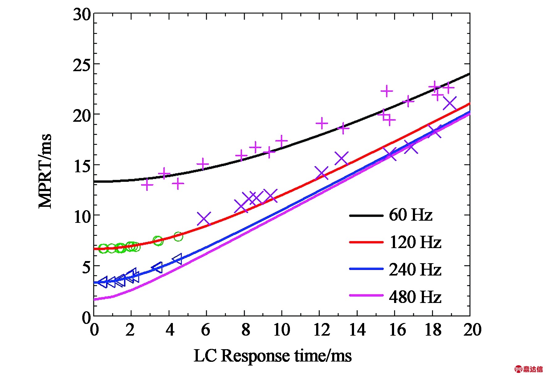
Fig.1 LC response time dependent MPRT. Solid lines represent the calculated data with Eq. (1), open dots, triangles, pluses, and crosses stand for measured results.
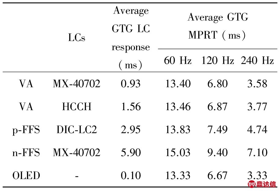
To achieve MPRT comparable to OLEDs, we developed ultra-low viscosity LC mixtures[8-10] for different LC modes, such as VA (Vertical Alignment) and FFS (Fringing-field-switching)[11]. Tab.1 summarizes the average GTG LC response time and MPRT at different TFT frame rates. An LCD TV employs multi-domain VA to achieve high contrast and wide view, and frame rate ≥120 Hz to reduce image blurs. On the other side, FFS is commonly used in smartphones and tablets as it exhibits weak color shift and pressure resistance. To lower power consumption, the frame rate is set at ≤60 Hz. For both p-FFS and n-FFS modes, their MPRT is 3% and 12% slower than that of OLED at f = 60 Hz, respectively. This difference becomes smaller if the frame rate is reduced to 30 Hz, because MPRT is less sensitive to the LC response time at low frame rate. However, the mobile phones and tablets are intended for static images, which do not need fast MPRT. Therefore, LCD and OLED exhibit comparable image performance in terms of motion blurs for TVs and monitors.
Tab.1 Average GTG LC response time and MPRT for different LCDs and OLED. Duty ratio=100%
2.1 CRT-like LCD
To achieve MPRT comparable to the impulse-driving CRT (~1.5 ms), three approaches are investigated: higher frame rate, backlight modulation, and combination of both. From Tab.1, if the frame rate is increased from 120 Hz to 240 Hz, the MPRT of VA LCD and OLED is reduced by ~2x yet remaining comparable (3.58 ms vs. 3.33 ms). The major tradeoffs of higher frame rate are twofold: increased electronic power consumption and shorter TFT charging time.
The second approach to reduce MPRT is through backlight modulation.Fig. 2 shows the simulation results of LC response time dependent MPRT with different duty ratios. The frame rate is f = 144 Hz, which is commonly employed in commercial gaming monitors. The limiting MPRT (i.e. τ=0) is reduced linearly when the backlight duty ratio (DR) decreases as:
MPRT=0.8×DR×Tf.
(2)
To suppress image blurs, Sony’s OLED TVs also employed 50% duty ratio[12], because MPRT decreases linearly with duty ratio. A low duty ratio helps to shorten MPRT, but the major tradeoff is decreased brightness and power efficiency. To compensate for the brightness loss, we can boost the LED backlight’s current. For OLED, in principle we can do the same impulse driving. However, high current impulse driving of OLED leads to substantial efficiency roll-off and lifetime degradation[13-14]. Similarly for LCD, high current driving of blue LED also suffers from droop effect[15]. However, the impact of droop effect to LED is substantially weaker than the declined efficiency and compromised lifetime to OLED.
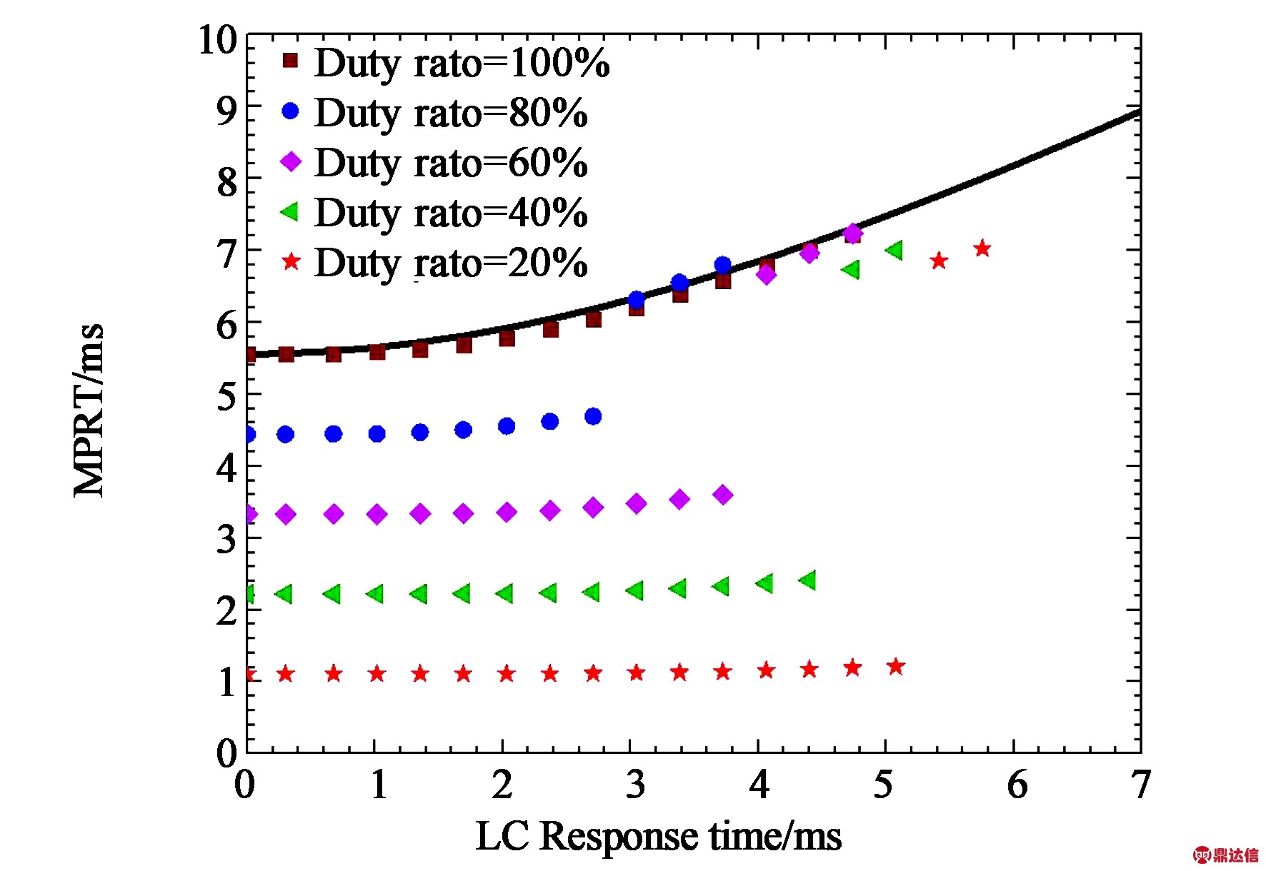
Fig.2 LC response time vs. MPRT with different duty ratios at f=144 Hz.
The third approach is to combine high frame rate with backlight modulation. From Eq. (2), if we increase the frame rate to 240 Hz while keeping duty ratio at ~45%, then we can achieve MPRT≈ 1.5 ms. However, the electronic power consumption is increased linearly with the frame rate. On the other hand, boosting the LED current to compensate for the brightness loss due to backlight modulation could also result in a higher power consumption, if the total brightness remains the same. Therefore, a proper combination between frame rate and duty ratio should be optimized, depending on the specific applications.
2.2 Fast-response LCDs
As depicted in Fig. 2, at a given frame rate and duty ratio, there exists an abrupt jump of MPRT as the LC response time increases. The LC response time at the jump is defined as the tolerable LC response time (τT). Therefore, to achieve a comparable MPRT to that of OLED with the same duty ratio, LC response time should be τ ≤ τT. If the frame rate is f = 144 Hz with 100% duty ratio, then τT ≈ 2 ms. But if we lower the duty ratio to 20%, then τT could increase to 5 ms. Such an operation mode greatly reduces the burden on LC response time. In the following part, we still set 2 ms as the targeted response time.
In addition to fast MPRT, high optical efficiency, wide viewing angle, weak color shift, and low operation voltage are equally important. Here, we briefly reviewd three LC modes with fast response time and wide view.
VA Mode: In Tab.1, we compare the measured results of VA LCDs with two low-viscosity LC mixtures: MX-40702 (from LC Vision) and HCCH-736700-100 (from HCCH, China). With overdrive and undershoot voltages[16], the average GTG response time of MX-40702 is only 0.93 ms. The corresponding MPRT is comparable to that of OLED at different frame rates. Besides, VA mode exhibits advantages of excellent dark state and high contrast ratio. Multi-domain VA (MVA) is a common approach to widen the viewing angle. The tradeoffs of MVA are twofold: lower transmittance and increased manufacturing complexity. To achieve wide view while keeping high transmittance, another option is to use single-domain VA with directional backlight and a diffusive element[17].
TN Mode:Chao et al. demonstrated a fast-response TN LCD using a low viscosity LC and thin cell gap[18]. The rise time is 0.66 ms and the decay time is 2.04 ms. With overdrive scheme, the average gray-to-gray response time is 1.95 ms. With such fast response time, the MPRT is comparable to the limiting MPRT (τ = 0), as shown in Fig. 1. For gaming monitors, the viewing angle of TN LCD is adequate. To widen the viewing angle, we can either add a Fuji compensation film[19] or use single-domain TN with directional backlight[17].
FFS Mode:FFS mode has advantages in wide view, weak color shift and pressure resistance for touch panels, but its response time is relatively slow because of its small K22 value. As Fig. 3(a) shows, the conventional FFS mode (using a positive △ε LC) has a typical rubbing angle θ≈ 5°~10°. It has been shown that the response time can be improved by setting θ= 0° [20-22]. Fig. 3(b) shows the working principle of such a FFS mode. With an applied voltage, the LC directors in the left region are reoriented in the clockwise direction, but those in the right region are in the counter-clockwise direction. The LC directors in the middle remain stationary, which work as a virtual wall to help improve the response time.
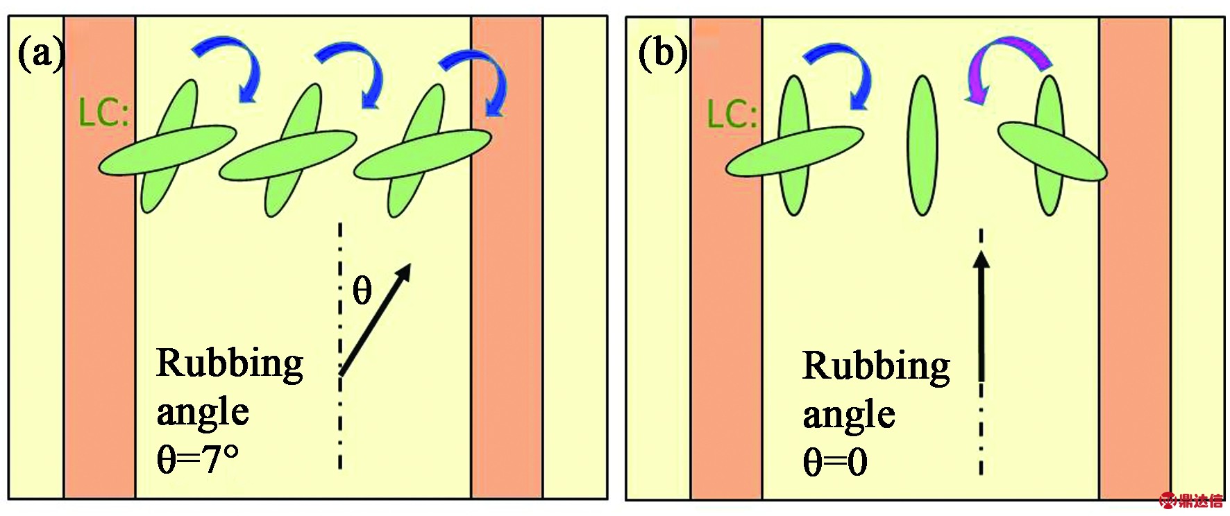
Fig.3 Top view of FFS cell with rubbing angle (a) θ = 7° and (b) θ = 0°.
Tab.2 Performance for FFS modes with different rubbing angles. The electrode width w = 2 μm and electrode gap l = 2.5 μm. Cell gap d = 2.5 μm

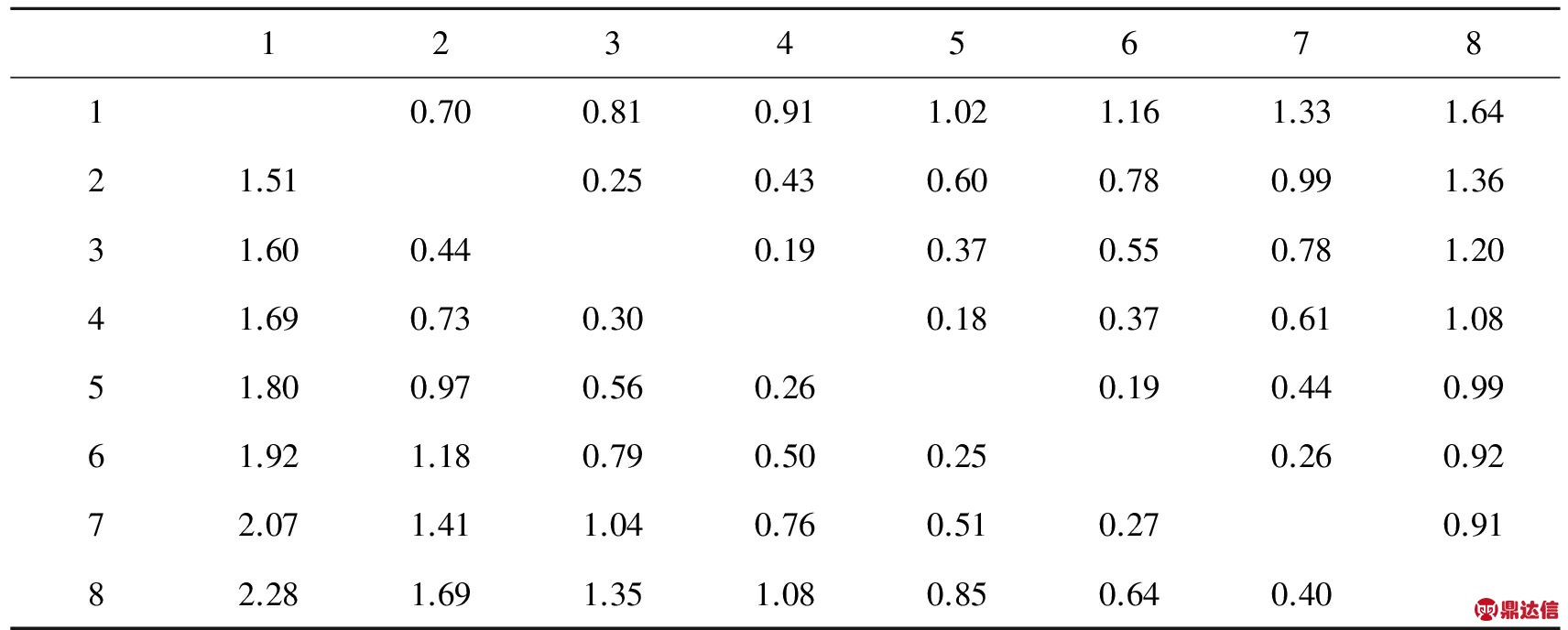
Tab.3 GTG response time of FFS cell with rubbing angle θ = 0 (ms)
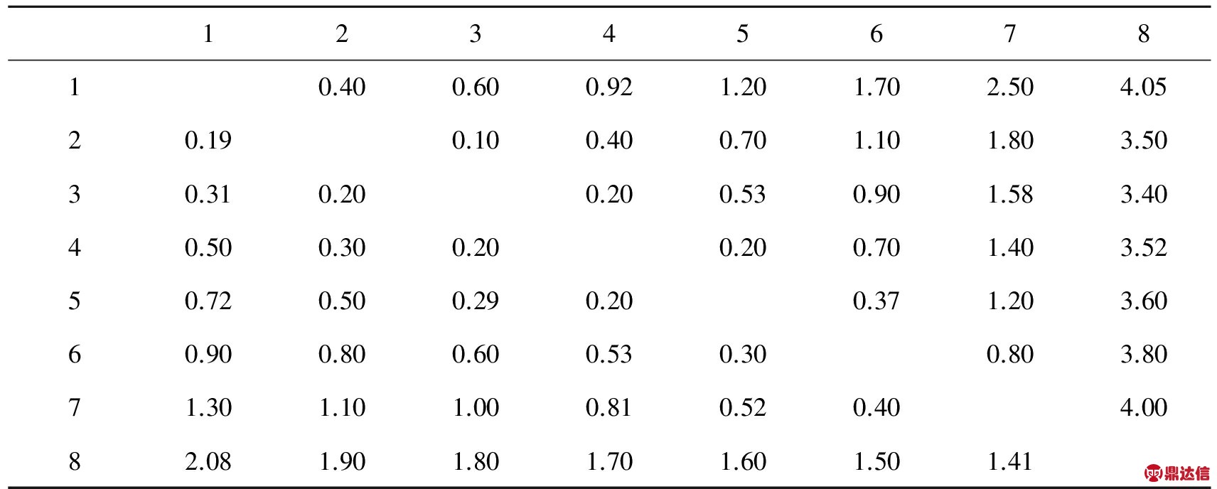
To achieve the targeted 2 ms response time, the LC parameters are assumed as: birefringence△n = 0.19 at λ =550 nm, △ε= 2.0 and rotational viscosity γ1 = 60 mPa·s. Tab.2 summarizes the performance for the FFS modes with rubbing angle θ = 7° and 0°, respectively. To make a fair comparison, we keep all the parameters the same except the rubbing angle. The FFS with θ = 0° shows 4x faster decay time, but the tradeoff is increased threshold voltage and decreased transmittance. Tab.3 summarizes the GTG response time for FFS with θ = 0°. After applying overdrive and undershoot driving scheme, the average response time is only 1.2 ms. In addition to fast response time, the FFS with θ = 0° exhibits a smaller off-axis color shift than that of single-domain FFS with θ > 0°.
VA-FIS Mode: Fig. 4(a) shows the cross-sectional view of VA-FIS (Fringing-In-plane-Switching) LCD [23]. The bottom substrate consists of a plane electrode (Vcom) and interdigital pixel electrodes (Electrodes 1 and 2). Voltages with the same magnitude but opposite polarity are applied to Electrodes 1 and 2, respectively. Besides, the top substrate is coated with a planar electrode in order to apply a biased voltage (Vbias). With Vbias = 5 V, both rise time and decay time are greatly improved.

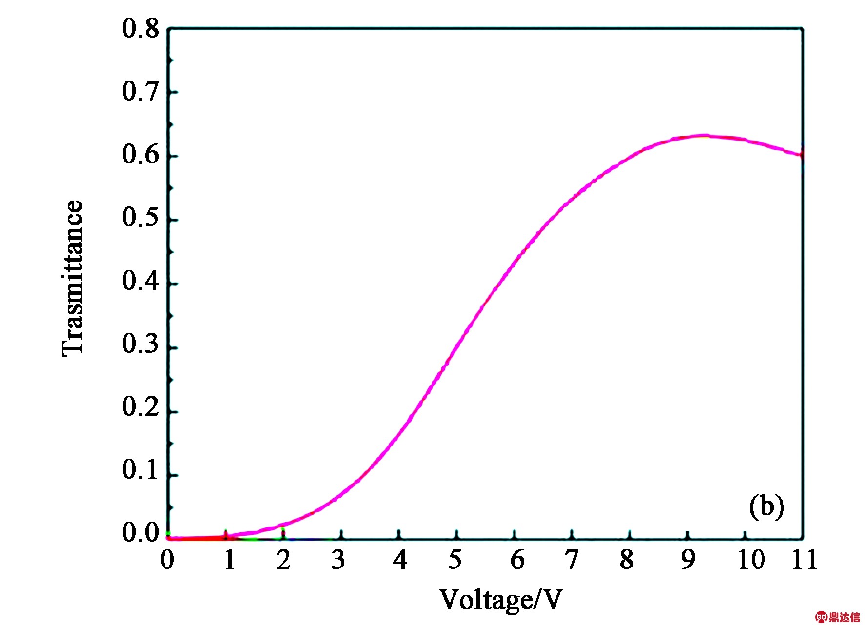
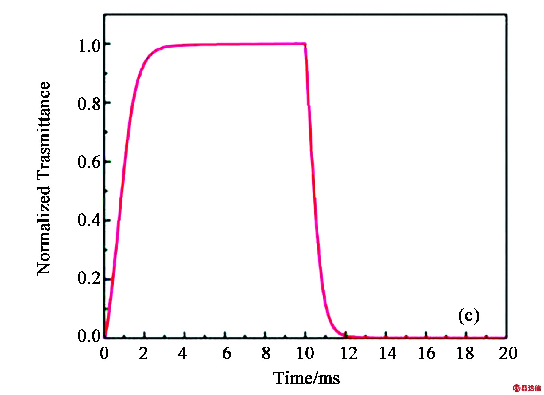
Fig.4 (a) The cross-sectional structure, (b) the simulated VT curve, and (c) the simulated time-dependent transmittance curve of a VA-FIS LCD
In the simulation, we set the electrode width w = 2 μm, gap l = 5 μm, and cell gap d = 4 μm. To reduce the operation voltage, LC with a relatively large Δε is employed. The LC parameters are: △n = 0.201 at λ =550 nm, △ε = 11 and rotational viscosity γ1 = 150 mPa·s. Figs. 4(b) and 4(c) show the V-T curve and T-T curve for the VA-FIS mode. The rise time is only 1.53 ms and decay time 0.97 ms. Because rise time and decay time are mainly controlled by the applied voltage, it maintains fast response time as well as fast MPRT at low temperatures (e.g. T = -30 ℃), which improves the image performance at extreme environment. However, the tradeoff is high operation voltage and low transmittance. At 9.3 V, the transmittance is only 63.3%. To boost transmittance, we can increase the electrode gap, but the voltage will also increase. Another method is to reduce Vbias by using a larger △ε LC, but the response time will be compromised.
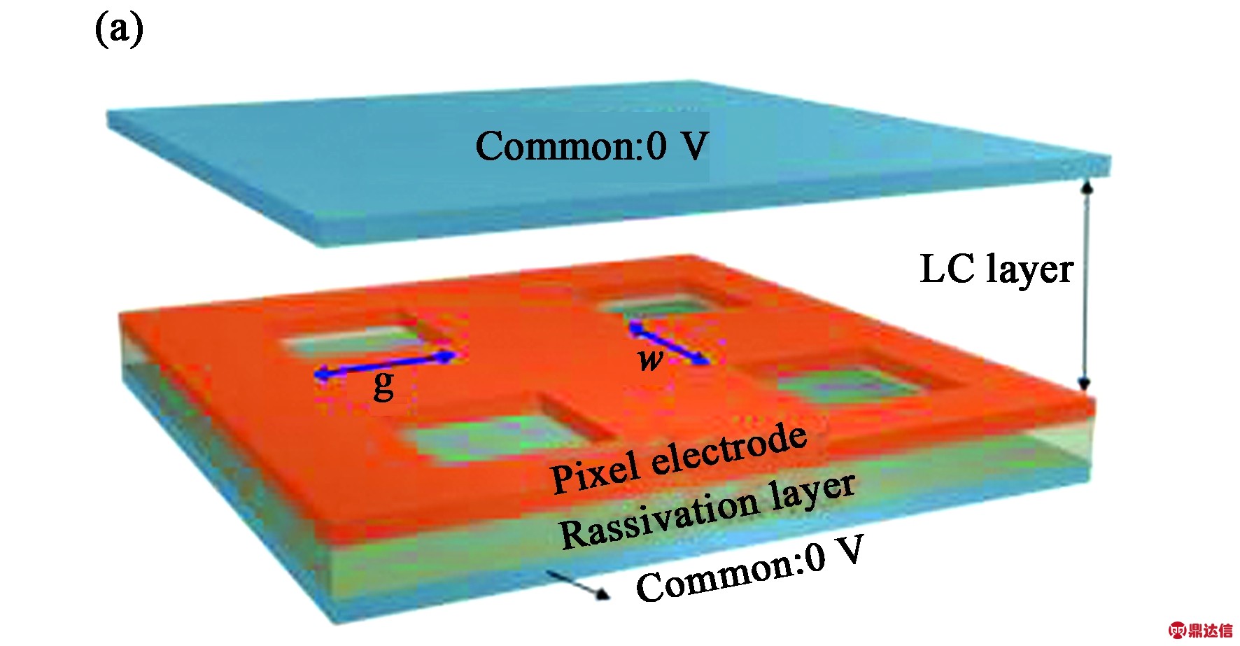
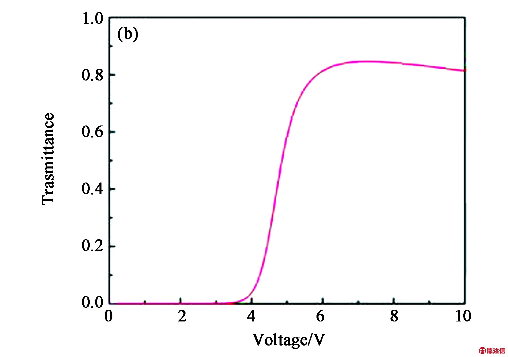
Fig.5 (a) 3D device structure of VA-FFS cell. (b) Voltage-dependent transmittance curve of VA-FFS cell with the g = 3 μm, w = 4 μm and cell gap d = 2.6 μm.
VA-FFS Mode:Fig. 5(a) depicts the 3D device configuration of VA-FFS cell[24]. The top substrate has a planar common electrode with Vcom = 0. The bottom substrate has three layers: (1) a common electrode with Vcom = 0; (2) a passivation layer and (3) pixel electrode with square-shaped holes. The bottom pixel electrode is similar to FFS mode, except for the 2D patterns, and negative △ε LC molecules are vertically aligned. The LC parameters are: Δn = 0.16 at λ = 550 nm, Δε = -3.3, K33 = 16.1 pN and γ1 = 95.2 mPa·s. Fig. 5(b) depicts the voltage-dependent transmittance (V-T) curve for the VA-FFS mode. Tab.4 lists the GTG response time of FFS-VA mode. With overdrive and undershoot driving scheme, the measured average GTG rise time and decay time are 0.75 ms and 1.03 ms, respectively. In addition, the VA-FFS mode enables a high aperture ratio because (1) only one TFT is needed per pixel and (2) bottom FFS electrodes have built-in capacitors. Therefore, high resolution is achievable. However, to improve the transmittance, VA-FFS requires two crossed circular polarizers.
Tab.4 GTG response time of VA-FFS cell (ms)
3 Summary
A simple equation to correlate the motion picture response time (MPRT) with LC response time and TFT frame rate is established.It is encouraging that LCD can achieve MPRT comparable to OLED. LC response time can be greatly improved by (1) employing an ultra-low viscosity LC and (2) developing fast-response LCD modes. To achieve CRT-like MPRT (≈1.5 ms), we could increase the TFT frame rate (say, 144 Hz) or reduce the backlight duty ratio.
Acknowledgments
The authors are indebted to DIC Corporation, Japan, for providing DIC-LC2 mixture.
References:
[1] SCHADT M. Milestone in the history of field-effect liquid crystal displays and materials [J].Japanese Journal of Applied Physics, 2009, 48(3S2): 03B001.
[2] KURITAT. Moving picture quality improvement for hold-type AM-LCDs [J]. SID Symposium Digest of Technical Papers, 2001, 32(1): 986-989.
[3] IGARASHI Y, YAMAMOTO T, TANAKA Y,et al. Proposal of the perceptive parameter motion picture response time (MPRT) [J]. SID Symposium Digest of Technical Papers, 2003, 34(1): 1039-1041.
[4] YAMAMOTO T, SASAKI S, IGARASHI Y, et al. Guiding principles for high-quality moving picture in LCD TVs [J]. Journal of the Society for Information Display, 2006, 14(10): 933-940.
[5] SLUYTERMAN A A S. What is needed in LCD panels to achieve CRT-like motion portrayal? [J]. Journal of the Society for Information Display, 2006, 14(8): 681-686.
[6] PENG F L, CHEN H W, GOU F W, et al. Analytical equation for the motion picture response time of display devices [J]. Journal of Applied Physics, 2017, 121(2): 023108.
[7] EMOTO M, KUSAKABE Y, SUGAWARA M. High-frame-rate motion picture quality and its independence of viewing distance [J].Journal of Display Technology, 2014, 10(8): 635-641.
[8] CHEN H W, HU M G, PENG F L,et al. Ultra-low viscosity liquid crystal materials [J]. Optical Materials Express, 2015, 5(3): 655-660.
[9] PENG F L, HUANG Y G, GOU F W,et al. High performance liquid crystals for vehicle displays [J]. Optical Materials Express, 2016, 6(3): 717-726.
[10] CHEN H W, PENG F L, GOU F W,et al. Nematic LCD with motion picture response time comparable to organic LEDs [J]. Optica, 2016, 3(9): 1033-1034.
[11] LEE S H, LEE S L, KIM H Y. Electro-optic characteristics and switching principle of a nematic liquid crystal cell controlled by fringe-field switching [J].Applied Physics Letters, 1998, 73(20): 2881-2883.
[12] ITO H, OGAWA M, SUNAGA S. evaluation of an organic light-emitting diode display for precise visual stimulation [J].Journal of Vision, 2013, 13(7), doi: 10.1167/13.7.6.
[13] MURAWSKI C, LEO K, GATHER MC. Efficiency roll-off in organic light-emitting diodes [J]. Advanced Materials, 2013, 25(47): 6801-6827.
[14] FÉRY C, RACINE B, VAUFREY D,et al. Physical mechanism responsible for the stretched exponential decay behavior of aging organic light-emitting diodes [J]. Applied Physics Letters, 2005, 87(21): 213502.
[15] VERZELLESI G, SAGUATTI D, MENEGHINI M,et al. Efficiency droop in InGaN/GaN blue light-emitting diodes: physical mechanisms and remedies [J]. Journal of Applied Physics, 2013, 114(7): 071101.
[16] WU S T. Nematic liquid crystal modulator with response time less than 100 μs at room temperature [J]. Applied Physics Letters, 1990, 57(10): 986-988.
[17] GAO Y T, LUO Z Y, ZHU R D,et al. A high performance single-domain LCD with wide luminance distribution [J]. Journal of Display Technology, 2015, 11(4): 315-324.
[18] CHAO A, HUANG K T, TSAI C W, et al. The fastest response TN-Type TFT LCD of the world likes OCB level [J]. SID Symposium Digest of Technical Papers, 2007, 38(1): 603-606.
[19] MORI H. The wide view (WV) film for enhancing the field of view of LCDs [J].Journal of Display Technology, 2005, 1(2): 179-186.
[20] MATSUSHIMA T, OKAZAKI K, YANGY, et al. New fast response time in-plane switching liquid crystal mode [J]. SID Symposium Digest of Technical Papers, 2015, 46(1): 648-651.
[21] CHOI T H, OH S W, PARK Y J,et al. Fast fringe-field switching of a liquid crystal cell by two-dimensional confinement with virtual walls [J]. Scientific Reports, 2016, 6: 27936.
[22] CHEN H W, TAN G J, HUANG Y G,et al. A low voltage liquid crystal phase grating with switchable diffraction angles [J]. Scientific Reports, 2017, 7: 39923.
[23] IWATA Y, MURATA M, TANAKA K, et al. Novel super fast response vertical alignment-liquid crystal display with extremely wide temperature range [J]. Journal of the Society for Information Display, 2014, 22(1): 35-42.
[24] GOU F W, CHEN H W, LI M C,et al. Submillisecond-response liquid crystal for high-resolution virtual reality displays [J]. Optics Express, 2017, 25(7): 7984-7997.
Author introduction:
High performance LCDs with CRT-like motion picture response time
Abstract:In order to analyze the image blur of displays, a simple equation to correlate the motion picture response time (MPRT) with LC response time and TFT frame rate is established. Three effective approaches to reduce MPRT are: (1) fast LC response time; (2) high frame rate, and (3) appropriate backlight duty ratio. At 120 Hz frame rate, if the LC’s response time is less than 2 ms, then its MPRT would be comparable to that of OLED. LC response time can be greatly improved by employing an ultra-low viscosity LC and developing fast-response LCD modes. To achieve CRT-like MPRT (less than 1.5 ms), we could increase the frame rate or decrease the duty ratio.
Key words:motion picture response time; fast response; liquid crystal displays
received:eng
received:her Ph. D. degree in Optics from College of Optics and Photonics, University of Central Florida, USA, in 2017. Her research interests include novel liquid crystal material development and device design for display and photonics applications. She has published 26 journal papers, received SID Distinguished Student Paper Awards four times, SPIE optics and photonics education scholarship, and IEEE (Orlando Section) outstanding graduate student scholarship and award. Haiwei Chen received his B. S. degree in optoelectronic information engineering from Beihang University, Beijing, China, in 2013 and is currently working toward the PhD degree at College of Optics and Photonics, University of Central Florida, USA. His research focuses on wide color gamut, high dynamic range, and fast-response liquid crystal display devices. He has published 35 journal papers, received SID Distinguished Student Paper Awards five times, and SPIE optics and photonics education scholarship. Fangwang Gou received her B. S. degree from University of Electronic and Science and Technology of China in 2012 and M. S. degree from Peking University, China, in 2015. Currently, she is working toward the PhD degree at College of Optics and Photonics, University of Central Florida, USA. Her current research interests include liquid crystal materials and devices for display and photonic applications. Shin-Tson Wu is Pegasus professor at College of Optics and Photonics, University of Central Florida. He is among the first six inductees of the Florida Inventors Hall of Fame (2014) and a Charter Fellow of the National Academy of Inventors (2012). He is a Fellow of the IEEE, OSA, SID, and SPIE, and the recipient of 2014 OSA Esther Hoffman Beller medal, 2011 SID Slottow-Owaki prize, 2010 OSA Joseph Fraunhofer award, 2008 SPIE G. G. Stokes award, and 2008 SID Jan Rajchman prize. Presently, he is serving as SID honors and awards committee chair.